Modbus RTU

Modbus RTU is an open, serial (RS-232 or RS-485) protocol derived from the Master/Slave architecture. It is a widely accepted protocol due to its ease of use and reliability. Modbus RTU is widely used within Building Management Systems (BMS) and Industrial Automation Systems (IAS). This wide acceptance is due in large part to MODBUS RTU’s ease of use.

MODBUS RTU messages are a simple 16-bit CRC (Cyclic-Redundant Checksum). The simplicity of these messages is to ensure reliability. Due to this simplicity, the basic 16-bit MODBUS RTU register structure can be used to pack in floating point, tables, ASCII text, queues, and other unrelated data.

ADCP (Acoustic Doppler Current Profiler)

An acoustic Doppler current profiler (ADCP) is a hydroacoustic current meter similar to a sonar, used to measure water current velocities over a depth range using the Doppler effect of sound waves scattered back from particles within the water column. The term ADCP is a generic term for all acoustic current profilers although the abbreviation originates from an instrument series introduced by RD Instruments in the 1980s. The working frequencies range of ADCPs range from 38 kHz to several Megahertz.

Working Principle

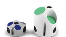
ADCPs with three beams resolve the three components of velocity. (Models Aquadopp Profiler 1MHz and 0.6 MHz, Nortek)

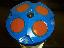
Head of an ADCP with four transducers (Model WH-600, RD Instruments)


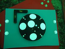
ADCPs contain piezoelectric transducers to transmit and receive sound signals. The traveling time of sound waves gives an estimate of the distance. The frequency shift of the echo is proportional to the water velocity along the acoustic path. To measure 3D velocities, at least three beams are required. In rivers, only the 2D velocity is relevant and ADCPs typically have two beams. In recent years, more functionality has been added to ADCPs (notably wave and turbulence measurements) and systems can be found with 2,3,4,5 or even 9 beams.

Further components of an ADCP are an electronic amplifier, a receiver, a clock to measure the traveling time, a temperature sensor, a compass to know the heading, and a pitch/roll sensor to know the orientation. An analog-to-digital converter and a digital signal processor are required to sample the returning signal in order to determine the Doppler shift. A temperature sensor is used to estimate the sound velocity at the instrument position using the seawater equation of state, and uses this to estimate scale the frequency shift to water velocities. This procedure assumes that the salinity has a preconfigured constant value. Finally, the results are saved to internal memory or output online to an external display software.

Underwater photo of an ADCP with five transducers (Model Signature1000, Nortek)

Processing Methods

Three common methods are used to calculate the Doppler shift and thus the water velocity along the acoustic beams. The first method uses a monochromatic transmit pulse and is referred to as “incoherent” or “narrowband”. The method is robust and provides good quality mean current profiles but has limited space-time resolution. When the transmit pulse consists of coded elements that are repeated, the method is referred to as “repeat sequence coding” or “broadband”. This method improves the space-time resolution by a factor of 5 (typical). Commercially, this method was protected by US patent 5615173 until 2011. The pulse-to-pulse coherent method relies on a sequence of transmit pulses where the echo from subsequent pulses are assumed not to interfere with each other. This method is only applicable for very short profiling ranges but the corresponding improvement in space time resolution is of order 1000.

Applications

Depending on the mounting, one can distinguish between side-looking, downward- and upward-looking ADCPs. A bottom-mounted ADCP can measure the speed and direction of currents at equal intervals all the way to the surface. Mounted sideways on a wall or bridge piling in rivers or canals, it can measure the current profile from bank to bank. In very deep water they can be lowered on cables from the surface.

The primary usage is for oceanography. The instruments can also be used in rivers and canals to continuously measure the discharge.

Mounted on moorings within the water column or directly at the seabed, water current and wave studies may be performed. They can stay underwater for years at a time, the limiting factor is the lifetime of the battery pack. Depending on the nature of the deployment the instrument usually has the ability to be powered from shore, using the same umbilical cable for data communication. Deployment duration can be extended by a factor of three by substituting lithium battery packs for the standard alkaline packs.

Bottom Tracking

By adjusting the window where the Doppler shift is calculated, it is possible to measure the relative velocity between the instrument and the bottom. This feature is referred to as bottom-track. The process has two parts; first identify the position of the bottom from the acoustic echo, then calculating the velocity from a window centered around the bottom position. When an ADCP is mounted on a moving ship, the bottom track velocity may be subtracted from the measured water velocity. The result is the net current profile. Bottom track provides the foundation for surveys of the water currents in coastal areas. In deep water where the acoustic signals cannot reach the bottom, the ship velocity is estimated from a more complex combination of velocity and heading information from GPS, gyro, etc.

Discharge Measurements

In rivers, the ADCP is used to measure the total water transport. The method requires a vessel with an ADCP mounted over the side to cross from one bank to another while measuring continuously. Using the bottom track feature, the track of the boat as well as the cross sectional area is estimated after adjustment for left and right bank areas. The discharge can then be calculated as the dot product between the vector track and the current velocity. The method is in use by hydrographic survey organizations across the world and forms an important component in the stage-discharge curves used in many places to continuously monitor river discharge.

DVL

For underwater vehicles, the bottom tracking feature can be used as an important component in the navigation systems. In this case the velocity of the vehicle is combined with an initial position fix, compass or gyro heading, and data from the acceleration sensor. The sensor suite is combined (typically by use of a Kalman filter) to estimate the position of the vehicle. This may help to navigate submarines, autonomous, and remotely operated underwater vehicles

The AWAC (Acoustic Wave and Currents) is a type of ADCP specifically designed for surface wave height and direction.

Wave Measurements

Some ADCPs can be configured to measure surface wave height and direction. The wave height is estimated with a vertical beam that measures the distance to the surface using the echo from short pulses and simple peak estimation algorithms. The wave direction is found by cross correlating the along-beam velocity estimates and the wave height measurement from the vertical beam. Wave measurements are typically available for seafloor-mounted instruments but recent improvements permit the instrument to be mounted also on rotating subsurface buoys.

Turbulence

ADCPs with pulse-to-pulse coherent processing can estimate the velocity with the precision required to resolve small scale motion. As a consequence, it is possible to estimate turbulent parameters from properly configured ADCPs. A typical approach is to fit the along beam velocity to the Kolmogorov structure configuration and thereby estimate the dissipation rate. The application of ADCPs to turbulence measurement is possible from stationary deployments but can also be done from moving underwater structures like gliders or from subsurface buoys.

Advantages and Disadvantages

The two major advantages of ADCPs is the absence of moving parts that are subject to biofouling and the remote sensing aspect, where a single, stationary instrument can measure the current profile over ranges exceeding 1000 m. This features allow for long term measurements of the ocean currents over a significant portion of the water column. Since the start in the mid-1980s, many thousand ADCPs have been used in the world oceans and the instrument has played a significant role in our understanding of the world ocean circulation.

The main disadvantage of the ADCPs is the loss of data close to the boundary. This mechanism, often referred to as a sidelobe interference, covers 6-12% of the water column and, for instruments looking up toward the surface, the loss of velocity information close to the surface is real disadvantage. Cost is also a concern but is normally dwarfed by the cost of the ship required to ensure a safe and professional deployment.

As any acoustical instrument, the ADCP contributes to noise pollution in the ocean which may interfere with cetacean navigation and echolocation. The effect depends on the frequency and the power of the instrument but most ADCPs operate in a frequency range where noise pollution has not been identified to be a serious problem.

Industry News: Flow Metering using Radar for Ex-Zone 1

The OFR flow sensor by NIVUS GmbH was approved for use in Ex-Zone 1 by TÜV Nord. In addition to ATEX approval required mainly in Europe the company was approved according to IECEx standard which is preferably demanded in English-speaking countries.

This allows contactless flow measurements in many applications including sewers. In order to obtain the Ex approvals a new sensor material was used and the sensor dimensions have been slightly modified. A non-Ex version of the radar sensor continues to remain available.

The flow sensor features IP 68 protection and thus is suitable for use particularly in harsh environments. In addition to the radar sensor NIVUS provide a modular holder bracket made of stainless steel for easy installation. The basic module enables mounting of the radar sensor. An extension allows installation of an extra IP 68 level sensor. Moreover the manufacturer provides an optional casing which covers both sensors in a compact enclosure.

Due to low space requirements the compact housing is suitable for installation even in cramped places or in locations where access is difficult. The contactless measurement and the compact construction of the radar system allow installation without the need to shut down processes.

Flow metering using radar sensors is suitable particularly for applications conducting aggressive or abrasive media. Another feature of the radar measurement system is the use in applications with shooting discharge and low flow levels.

https://www.chromatographytoday.com/news/water-wastewater/9/nivus-gmbh/flow-metering-using-radar-for-ex-zone-1/41747

Industry News: Hybrid Metering System for Flow Rate Detection

Introducing the new NivuFlow 7550 from Nivus GmbH, the measurement systems manufacturer from now on provides a hybrid metering system for flow rate detection besides measurement systems based on ultrasound and radar technology. In addition to flow velocity determination using radar the transmitter is designed to detect velocities by using the ultrasonic cross correlation method. So the complete measurement system is equipped with two flow velocity sensors, one level sensor and the NivuFlow 7550 hybrid transmitter.

Depending on the sensor installation position and the filling level there are two basic applications for hybrid metering: hybrid metering as measurement range extension (e.g. impounding in canals) to make sure the measurement covers the entire range and hybrid metering as redundant systems to increase accuracy.

The hybrid measurement system benefits from the advantages of both technologies. Thanks to the ultrasonic cross correlation method the velocities are measured in various flow levels. This not only enables to map the flow profile but also to increase the accuracy of the entire system. The radar sensor is installed outside of or above the medium and hence is ideally suited for applications featuring sedimentation. Measuring the surface velocity using radar moreover helps to increase the determination of the hydraulic model prevailing.

Upon request the complete system is also available for use in Ex zone 1.

The compact transmitter design permits easy and space-saving installation in control cabinets using DIN rails. A field enclosure is available for outdoor use.

The graphic display and the transmitter’s intuitive operating concept allow quick and easy commissioning of the flow measurement system. Thanks to extended diagnostic options running processes can be analysed professionally directly on site. Flow rates are calculated based on latest fluid-dynamical models. Furthermore the unit provides remote maintenance options via Internet.

https://www.chromatographytoday.com/news/water-wastewater/9/nivus-gmbh/hybrid-metering-system-for-flow-rate-detection/42367

Industry News: New NIVUS Radar Transmitter

Introducing the NivuFlow 550 NIVUS present an easy-to-operate flow metering transmitter

The new transmitter in combination with a radar sensor enables contactless flow measurement in open channels and part filled pipes. To accurately detect and to compute flow rates NIVUS have developed new dynamic hydraulic models. These models have been created for the widest range of canal shapes based on alternating filling levels.

Upon request the system is also available for use in Ex zone 1.

The compact transmitter design permits easy and space-saving installation in control cabinets using DIN rails. A weatherproof cover for outdoor use is available even in IP 68.

The graphic display and the intuitive operating concept of the NivuFlow 550 allow quick and easy commissioning of the flow measurement system. Thanks to extended diagnostic options running processes can be analyzed professionally directly on site. Furthermore the unit provides remote maintenance options via Internet.

Flow metering using the radar sensor is suitable mainly for applications featuring aggressive or abrasive media. Moreover the radar measurement system is ideal for applications with sedimentation since the radar sensor is fastened outside of or above the medium. Furthermore NivuFlow 550 stands out for the use even in applications with shooting discharge and low flow levels.

https://www.chromatographytoday.com/news/flow-level-pressure/12/nivus-gmbh/new-radar-transmitter/43523

Industry News: NIVUS Wins Water Dragon Award 2016

After winning the regional heat at Severn Trent’s Headquarters back in September the manufacturer of high accurate flow measurement systems wins the national UK Innovation Award with their Cross Correlation Pipe Sensor. The NIVUS team picked up its award at the Future Water Association’s annual lunch which was held at the Pump Rooms in Leamington Spa on 23rd February 2017.

The award winning flow sensor measures the flow directly within the pipe which is far superior to regular Clamp-On-Systems which can only measure from the outside. Why go to the concert and only listen behind the door?  Nivus advanced  technology and superior signal quality equals more reliable measurement results. Considered a game changer the NIVUS solution proves to be smart. Benefits are numerous, easy installation without shutting down the flow is distinctly advantageous as well as delivering a low carbon footprint.

The judges were impressed by the unique flow sensing technology developed by NIVUS which creates an audio image of particles within the wastewater to increase the flow measurement accuracy. Furthermore they gave recognition for the easy installation which allows the insertion/removal without the need for ‘pipe shutdown’ as well as delivering the Totex based solution for the application favorably compared to existing flow measurement devices. And not least the judges also commended Alison Southwood and David Miles for a strong presentation clearly defining the business case.

David Miles, Business Manager for NIVUS in the UK explains the importance of winning this award, “This recognition for our Cross Correlation Pipe Sensor comes at an exciting time for NIVUS as we are seeing some fantastic results on sites throughout the UK on both fresh and waste water systems. Combining our technology with existing applications is proving highly successful as for the first there is now a method for achieving a true and accurate measurement of flow”

NIVUS UK Innovation Manager, Alison Southwood, convinced the audience with the advantages of the pipe sensor solution. She states, “Winning the Innovation Award is a reward for all the efforts we put in developing the high accurate and easy to handle measurement system. Now we are looking forward to using this valuable endorsement to promote the advantages of our smart flow measurement solution to a wider audience.”

https://www.chromatographytoday.com/news/water-wastewater/9/nivus-gmbh/nivus-wins-water-dragon-award-2016/42505

Radar Takes on Open Channel Flow Measurement

In recent years level devices using radar have seen tremendous growth in uses requiring precision measurement, in part because of their ability to overcome such level measurement problems as foaming, temperature changes, vapors, condensates and surface agitation.

Unlike acoustic devices, where the accuracy of the device is affected by the temperature effects on the speed of sound, radar devices are virtually immune to such errors. Now, flow sensors incorporating radar are entering the open channel flowmeter marketplace providing non-contact flow measurement.

A basic principle of radar is its ability to reflect off the surface of materials based on the material’s dielectric constant. Any material that has a dielectric constant greater than 2, such as water or ammonia, will easily reflect radar signals. The higher the dielectric constant of the material, the more signal that is reflected and available for processing. On the other hand, radar signals tend to pass through materials that have a dielectric constant less than 2, such as air, vapor, certain gases, or foam, and therefore these materials have a minimal effect on level and velocity measurements as compared with other measurement technologies.

Radar flowmeters determine the velocity of the flow similar to how police radar guns measure the velocity of an automobile. The radar beam is transmitted from the sensor’s “horn” at a defined angle to the flow surface.
This transmitted beam interacts with the fluid and reflects back a portion of the transmitted signal. The portion of the signal that is reflected back is at a slightly different frequency than that which was transmitted. For instance, the frequency is slightly higher if the flow is coming toward the beam and is slightly lower if the flow is going away from the beam.

The reflected signals that return to the radar horn are detected and compared with the transmitted frequency.

The frequency shift is a direct measure of both the velocity and direction of the flow particles from which the signal was reflected. Operating at a relatively high frequency, the radar flowmeter can measure velocities with only a minimum amount of surface disturbance.

In all open channels, the flow varies throughout the cross-section. These “velocity profiles” generally terminate along the surface of the flow. In other words, a fingerprint of the flow profile exists on the flow surface itself. By measuring a portion of this fingerprint, the radar flowmeter can determine the average velocity of the flow stream.

Because the position of the beam relative to the flow surface is known, the relationship between the sensed velocity and the average velocity of the flow stream is defined and flow can be determined to an accuracy of ± 5 percent or better. Like all flow metering devices, the flow needs to be reasonably uniform in nature to obtain the highest accuracy.

The non-contact nature of the radar open channel flowmeter reduces the need for periodic maintenance and helps limit sensor fouling. Also, radar flowmeters can operate from above existing channels without the need of flumes or weirs and without any limitation on the minimum or maximum flow range.

Source: http://www.waterworld.com/articles/print/volume-14/issue-8/automation-technology/radar-takes-on-open-channel-flow-measurement.html

Remote Terminal Unit (RTU)

A remote terminal unit (RTU) is a microprocessor-controlled electronic device that interfaces objects in the physical world to a distributed control system or SCADA (supervisory control and data acquisition) system by transmitting telemetry data to a master system, and by using messages from the master supervisory system to control connected objects. Other terms that may be used for RTU is remote telemetry unit or remote telecontrol unit.

Architecture

An RTU monitors the field digital and analog parameters and transmits data to the Central Monitoring Station. It contains setup software to connect data input streams to data output streams, define communication protocols, and troubleshoot installation problems.

An RTU may consist of one complex circuit card consisting of various sections needed to do a custom fitted function or may consist of many circuit cards including CPU or processing with communications interface(s), and one or more of the following: (AI) analog input, (DI) digital input, (DO/CO) digital or control (relay) output, or (AO) analog output card(s).

Power supply

A form of power supply will be included for operation from the AC mains for various CPU, status wetting voltages and other interface cards. This may consist of AC to DC converters where operated from a station battery system.

RTUs may include a battery and charger circuitry to continue operation in event of AC power failure for critical applications where a station battery is not available.

Digital or status inputs

Most RTUs incorporate an input section or input status cards to acquire two state real world information. This is usually accomplished by using an isolated voltage or current source to sense the position of a remote contact (open or closed) at the RTU site. This contact position may represent many different devices, including electrical breakers, liquid valve positions, alarm conditions, and mechanical positions of devices.

Analog inputs

A RTU can monitor analog inputs of different types including 0-1 mA, 4–20 mA current loop, 0–10 V., ±2.5 V, ±5.0 V etc. Many RTU inputs buffer larger quantities via transducers to convert and isolate real world quantities from sensitive RTU input levels. An RTU can also receive analog data via a communication system from a master or IED (intelligent electronic device) sending data values to it.

The RTU or host system translates and scales this raw data into the appropriate units such as quantity of water left, temperature degrees, or Megawatts, before presenting the data to the user via the human–machine interface.

Digital (control) outputs

RTUs may drive high current capacity relays to a digital output (or “DO”) board to switch power on and off to devices in the field. The DO board switches voltage to the coil in the relay, which closes the high current contacts, which completes the power circuit to the device.

RTU outputs may also consist of driving a sensitive logic input on an electronic PLC, or other electronic device using a sensitive 5 V input.

Analog outputs

While not as commonly used, analog outputs may be included to control devices that require varying quantities, such as graphic recording instruments (strip charts). Summed or massaged data quantities may be generated in a master SCADA system and output for display locally or remotely, wherever needed.

Software and logic control

Modern RTUs are usually capable of executing simple programs autonomously without involving the host computers of the DCS or SCADA system to simplify deployment and to provide redundancy for safety reasons. An RTU in a modern water management system will typically have code to modify its behavior when physical override switches on the RTU are toggled during maintenance by maintenance personnel. This is done for safety reasons; a miscommunication between the system operators and the maintenance personnel could cause system operators to mistakenly enable power to a water pump when it is being replaced, for example.

Maintenance personnel should have any equipment they are working on disconnected from power and locked to prevent damage and/or injury.

Communications

A RTU may be interfaced to multiple master stations and IEDs (Intelligent Electronic Device) with different communication media (usually serial (RS232, RS485, RS422) or Ethernet). An RTU may support standard protocols (Modbus, IEC 60870-5-101/103/104, DNP3, IEC 60870-6-ICCP, IEC 61850 etc.) to interface any third party software.

Data transfer may be initiated from either end using various techniques to insure synchronization with minimal data traffic. The master may poll its subordinate unit (Master to RTU or the RTU poll an IED) for changes of data on a periodic basis. Analog value changes will usually only be reported only on changes outside a set limit from the last transmitted value. Digital (status) values observe a similar technique and only transmit groups (bytes) when one included point (bit) changes. Another method used is where a subordinate unit initiates an update of data upon a predetermined change in analog or digital data. Periodic complete data transmission must be used periodically, with either method, to insure full synchronization and eliminate stale data. Most communication protocols support both methods, programmable by the installer.

Multiple RTUs or multiple IEDs may share a communications line, in a multi-drop scheme, as units are addressed uniquely and only respond to their own polls and commands.

IED communications

IED communications transfer data between the RTU and an IED. This can eliminate the need for many hardware status inputs, analog inputs, and relay outputs in the RTU. Communications are accomplished by copper or fibre optics lines. Multiple units may share communication lines.

Master communications

Master communications are usually to a larger control system in a control room or a data collection system incorporated into a larger system. Data may be moved using a copper, fiber optic or radio frequency communication system. Multiple units may share communication lines.

Comparison with other control systems

RTUs differ from Programmable Logic Controllers (PLCs) in that RTUs are more suitable for wide geographical telemetry, often using wireless communications, while PLCs are more suitable for local area control (plants, production lines, etc.) where the system utilizes physical media for control. The IEC 61131 programming tool is more popular for use with PLCs, while RTUs often use proprietary programming tools.

RTUs, PLCs and DCS are increasingly beginning to overlap in responsibilities, and many vendors sell RTUs with PLC-like features and vice versa. The industry has standardized on the IEC 61131-3 functional block language for creating programs to run on RTUs and PLCs, although nearly all vendors also offer proprietary alternatives and associated development environments.

In addition, some vendors now supply RTUs with comprehensive functionality pre-defined, sometimes with PLC extensions and/or interfaces for configuration.

Some suppliers of RTUs have created simple graphical user interfaces GUI to enable customers to configure their RTUs easily. In some applications dataloggers are used in similar applications.

A Programmable Automation Controller (PAC) is a compact controller that combines the features and capabilities of a PC-based control system with that of a typical PLC. PACs are deployed in SCADA systems to provide RTU and PLC functions. In many electrical substation SCADA applications, “distributed RTUs” use information processors or station computers to communicate with digital protective relays, PACS, and other devices for I/O, and communicate with the SCADA master in lieu of a traditional RTU.

Applications

  • Remote monitoring of functions and instrumentation for:
    • Oil and gas (offshore platforms, onshore oil wells)
    • Networks of pump stations (waste water collection, or for water supply)
    • Environmental monitoring systems (pollution, air quality, emissions monitoring)
    • Mine sites
    • Air traffic equipment such as navigation aids (DVOR, DME, ILS and GP)
  • Remote monitoring and control of functions and instrumentation for:
    • Hydro-graphic (water supply, reservoirs, sewage systems)
    • Electrical power transmission networks and associated equipment
    • Natural gas networks and associated equipment
    • Outdoor warning sirens

Source: https://en.wikipedia.org/wiki/Remote_terminal_unit

Datalogger

A datalogger is an electronic device that records data over time or in relation to location either with a built in instrument or sensor or via external instruments and sensors. Increasingly, but not entirely, they are based on a digital processor (or computer). They generally are small, battery powered, portable, and equipped with a microprocessor, internal memory for data storage, and sensors. Some data loggers interface with a personal computer, and use software to activate the data logger and view and analyze the collected data, while others have a local interface device (keypad, LCD) and can be used as a stand-alone device.

Data loggers vary between general purpose types for a range of measurement applications to very specific devices for measuring in one environment or application type only. It is common for general purpose types to be programmable; however, many remain as static machines with only a limited number or no changeable parameters. Electronic data loggers have replaced chart recorders in many applications.

One of the primary benefits of using data loggers is the ability to automatically collect data on a 24-hour basis. Upon activation, data loggers are typically deployed and left unattended to measure and record information for the duration of the monitoring period. This allows for a comprehensive, accurate picture of the environmental conditions being monitored, such as air temperature and relative humidity.

The cost of data loggers has been declining over the years as technology improves and costs are reduced. Simple single channel data loggers cost as little as $25. More complicated loggers may costs hundreds or thousands of dollars.

Four Level Measuring Technologies


With a variety of different level measuring devices available today, it is easy to be confused about which type of measuring device would be best suited for a particular application.  Provided below is a brief overview of four specific level measuring technologies: Ultrasonic, Capacitance, Hydrostatic, and Radar. For all of these above mentioned technologies, highlighted below is the basic operating principle of each, some application examples, as well as advantages and disadvantages of these technologies.

Hydrostatic Operating Principle

Hydrostatic operating level devices are based on the principle that fluids exert a pressure that is a function of height. Submersible level sensors work by measuring that hydrostatic pressure formed by the water column directly located above the unit and output a linear 4-20mA output proportional to level. The piezoresistive pressure sensor is suspended below the level, and the output is then correlated to a level reading in feet or meters of water column. Hydrostatic pressure instruments, such as Dwyer’s’ submersibles, are provided at the lowest cost when compared to other liquid level sensing technologies. They feature easy installation with characteristic differences to suit a variety of applications. The Dwyer Series SBLT and MBLT feature small pressure openings that work great in clean water applications, with the MBLT featuring a small, 0.63”, housing diameter for borehole applications. For more robust units we offer our Series PBLT and FBLT with no pressure openings making them ideal for sludges and slurries.  Some advantages of this level technology is that it is great for applications that may contain vapor, foam, or any form of agitation.  Some disadvantages of submersibles are that you are limited by the use of only low viscosity liquids with a specific measuring range, compatibilty to the wetted material, and they can only be used in non-pressurized tank applications.  Standard units are calibrated for water and any other fluid application with a SG variance, although water needs to be accounted for to maintain the accuracy of the unit. Another important note is that these units measure the pressure difference in reference to atmospheric pressure, so it is important that the breathing tube or vent tube of the unit be properly vented to the atmosphere and clear of any obstructions. The vent tube must also be free of any moisture that could condense, harming the electrical components. Our units are supplied with a hydrophobic, Teflon filter in order to avoid any moisture build up, with an option to purchase our A-297 reusable desiccant filter accessory, for higher moisture environments.  

Ultrasonic Operating Principle
Ultrasonic level sensors work by emitting high frequency acoustic signals that are reflected back and detected by the unit. The transit time of the signal, from the sensor to the target and back to the sensor is correlated to the level.  Some advantages in using an ultrasonic level sensor are that it provides a non-contact measurement, which virtually eliminates any compatibility concerns and is great for measuring the level of high viscous liquids, with no regards to the SG. The full measuring range of the ultrasonic is programmable and features a high F.S. accuracy. Ultrasonics can be used to measure level height in flumes and weirs in order to calculate open channel flow, as offered with our Series ULF. Some disadvantages of ultrasonic level sensing is that it is not to be used in high turbulence applications or applications that may have steam, foam, or high variances in the concentration of the process material. Turbulence and foam prevent the sound wave from being properly reflected back to the sensor, while steam and vapors absorb the acoustic signal. A stilling well may be used to prevent some of these issues but should be considered before purchasing an ultrasonic for these applications. High pressurized tanks or ones under vacuum have different sound coefficients and ultrasonics can be affected by the changing coefficient of sound due to moisture, temperature, or pressure.  Consequentially, it is important to understand that due to characteristics of sound waves when these changes exist in an application they may lead to inaccuracies, as well as a lost signal. Correction factors can be applied to the level measurement to improve the accuracy of measurement and is offered in the programing structure of our Series UTC and UTS. Direct overhead installation is required for the proper use of the unit making installation sometimes difficult. Since the unit is transmitting and receiving ultrasonic signals there is a small distance located at the end of the sensor where there are some mechanical vibrations that must be overlooked by the sensor in order for unit to accurately measure the level height. This small distance is known as the dead band and must be taking into account when looking level height of the process. Our Series ULT features software mapping to deal with tank intrusions such as ladders, pipes, or agitators, small dead band, and features an effective sensing area of only 7.6 cm or 3”.
Capacitive Operation
Capacitive units utilize low radio frequency to measure the conductivity of current in a closed circuit that varies proportionally to the level of the application. It’s important to remember that capacitance is a function of the dialectic constant of the fluid, the surface area of the capacitor, the probe, and the separation distance. All constants must maintain the same with only the level of the media allowed to change. Some advantages of capacitive units is the vertical mounting, the FEP coating that increases chemical compatibility, and the fact that it works well in liquids with solids. Capacitance level units are not affected by dust, foam or varying specific gravity, and feature a programmable range. Some disadvantages to using capacitance level probes is that when it is used in applications with non-metallic tanks or tanks with irregularly shaped walls a probe ground reference must be used to properly operate and therefore must be purchased at time of order. It is also important that the dielectric constant of the measuring media is greater than 3mF and is used for measuring heights greater than 6in for water (other liquids as permitted by their dielectric constant).  As noted capacitance is a product of the surface area and therefore we discourage the purchase of a probe length less than 24” in length.  
Guided Wave Radar
Guided wave radar utilizes what is referred to as TDR or Time Domain Reflectometry technology. With this technology, impulses are transmitted along the probe at fast rates to the surface of the fluid and when these impulses hit the fluid a portion of the signal is reflected back up the probe. The time between the signal transmittal and receipt is used to determine the fluid level. Advantages of using radar are the top vertical mounting and the fact that it can be used with liquids with floating solids or coating liquids. Other added features of this technology is that it is unaffected by emulsification, dust, foam or vapors and it features a programmable output range, which is unaffected by dielectric or specific gravity changes of the liquid, with no real minimum probe length requirement. Some disadvantages of this technology are that the probe length must be the entire length of the sensing range and is typically offered at a higher cost. Attention must be taken when choosing the proper probe type in applications with bypass chambers or stilling wells. Overall, there are vast amounts of ways to measure fluid level and every level measuring technology isn’t created equal. In order to avoid confusion and sometimes costly reinstallation fees, contact Tardigraz Technologies for more information on which level technology is best suited for your application.